Sony KV-27V66 RGB mod
Why and background information
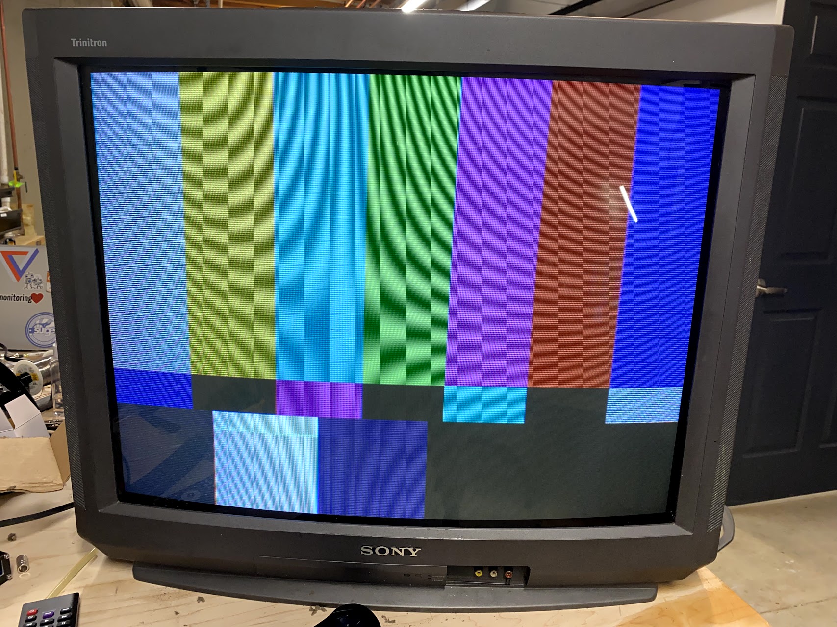
The Sony KV-27V66 is a 27 inch CRT TV, with the famous Trinitron tubes and a BA-4D chassis. Unfortunately, it only exposes Composite and S-Video inputs. While S-Video isn’t that bad, we can probably do better by modding it to accept RGB signals. You can read and learn more about RGB modding and it’s advantages here and a lot of more information about modding TVs on this shmups forum thread. This should probably work on the 27V42 and other BA-4D chassis as long as they have the same or similar Jungle ICs.
Hint
While this RGB mod works and it’s theoretically the best way to do it, it’s maybe a little too complicated. We made it mostly to prove a point. There are easier alternatives for the BA-4D chassis based Trinitron TVs: Component Video mod and RGB Mux mod.
Documents you may want to get acquainted with:
- 27V66 Service Manual
- CXA2061S datasheet
Info
The Service Manual shows that the TV uses a CXA2133S Jungle chip, we weren’t able to find a datasheet for it anywhere. The CXA2061S data sheet is a pin match, and the I²C information matches probably 90% of what We investigated so We will assume they are the same for all intent and purposes.
Methods and problems
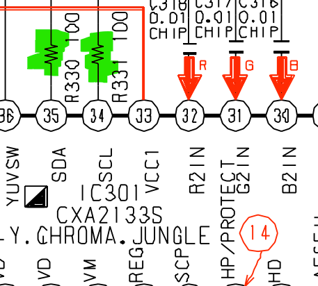
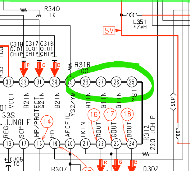
The TV Jungle chip has a second, unused, RGB input. Those are on the pins 26-28, with a YS1 selector on pin 25. Putting voltage between 0.7 and 7 volts on that YS1 pin selects the input, unless the RGB SEL register on the Jungle memory is set to 1. Of course, Sony sets that to 1 by default, so our mission here is to revert that heresy.
There are many methods to do that, Adam aka PCBJunkie has a very good video and article about finding and defeating the i2c commands for a different model. We tried that method but We wasn’t able to make an Arduino work fast enough to deal with the changes. A second method is the one used by Martin from immerhax.com to fix the RGB on some JVC monitors, and that’s the basis of our current method.
Basically what we are going to do is to intercept the i2c communication between the Micom and Jungle chips, watch for certain registers to be written/read and change the values on the fly.
I²C analysis and findings
So the first thing was to find out what is the normal initialization procedure on the TV, so we could find what kind of change we would need. We hooked up a logic probe to the I²C bus and watched specifically for the 0x44 slave address (that is the Jungle IC 7-bit address).
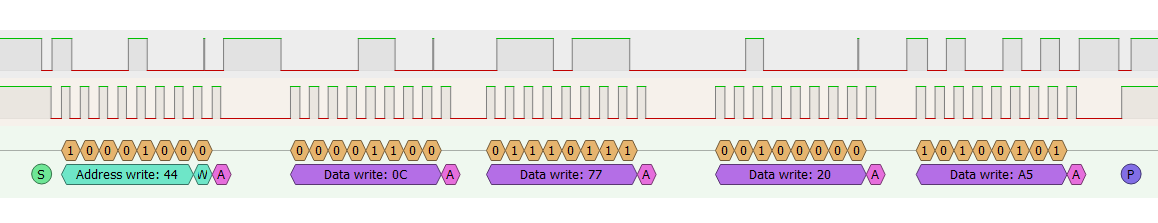
So the Micom writes data to the Jungle registers (described on page 17 of the datasheet) in groups of 3 registers at a time. So on that capture above we have the write starting at address 0xC and then writing three bytes, so it writes the registers 0xC, 0xD, and 0XE. In the datasheet they are in binary but they are the registers 12 (1100), 13(1101), and 14 (1110).
| Register | Bit7 | Bit6 | Bit5 | Bit4 | Bit3 | Bit2 | Bit1 | Bit0 |
|---|---|---|---|---|---|---|---|---|
| xxx01100 | H OSC | * | * | * | * | |||
| xxx01101 | * | * | CD MODE | INTERLACE | H SS | V SS | ||
| xxx01110 | V SIZE | * | H MASK |
The register we are trying to change is the RGB SEL one, that is on address 0xA, but since the Micom sends that data in groups of three, it will actually be contained on the second byte of the 0x9 register data.
Quote
RGB SEL (1): Disables YS1 switch selection and prohibits external signal input from RGB1.
0 = YS1 normal mode
1 = YS1 forced OFF mode
And, as expected, the Micom does indeed send a 1 there:
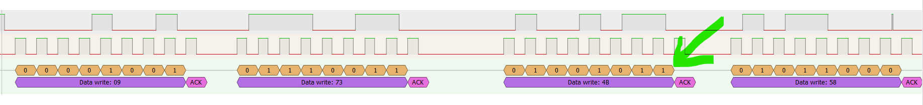
So all we have to do now is flip that last bit and make that 0x4B (0b01001011) into a 0x4A (0b01001010). We tried manually flipping that data with a Bus Pirate, but the Micom constantly rewrites that register, so we guess Sony really didn’t wanted that bit to be on.
Status Register
The second, and maybe most important, thing on the Jungle I²C is Status Register read, that the Micom repeats every second or so. It simply read the two bytes from the Jungle Status Register to decide if the IKR bit (related to the self diagnostic circuit) is set to 1 or not. If that’s false, the CRT cannon is shut off or the whole set turns down. We will then have to make sure the Micom receives the correct status for this to work.
| Bit7 | Bit6 | Bit5 | Bit4 | Bit3 | Bit2 | Bit1 | Bit0 | |
|---|---|---|---|---|---|---|---|---|
| First Byte | HLOCK | IKR | VNG | HNG | KILLER ID OFF | 0 | 0 | 0 |
| Second Byte | HCENT | 0 | 0 | 0 | 1 | 0 | 0 | 1 |
Arduino it up
So now that we know what to do and why, all we need is to get an arduino midway there and change the data when needed. We tried many approaches, some worked better than others. Currently, the one we are using and probably is the most cost saving and hand soldering friendly one is to use a Pro Micro Arduino that is a smaller version of a Leonardo and have been used a lot for custom keyboards and other USB based applications.
The Pro Micro is small, has 5V pin logic, one I²C interface that we will use as Slave, and can be powered by up to 9V so we don’t need to worry about that either. It also has enough speed to be able to run a software I²C master in a speed that isn’t causing us problem.
Note
We also made a version using a Black Pill STM32F303 that is a monster MCU for this and totally unnecessary. It has two I²C interfaces so we don’t need to worry about bus speed, but it needs level shifting (since it’s a 3.3V logic MCU) and a power source since we don’t have good places to get enough amps on a 5V standby power.
The code is available at Github, it’s a Platform.io project but it should be a 1:1 copy/paste situation to the Arduino IDE. It is also heavily commented so there’s not much we can add here, use the source, Luke.
The gist of the code is:
- Setup an I²C slave using the hardware interface to receive the data from the Micom
- Setup an I²C master using
SoftI2CMasterto talk exclusively to the Jungle - Listen to all communication intended to the Jungle and add them to a circular buffer/FIFO
- Process the buffer sending data to the Jungle, altering the registers/values that we need
- Listen to all requests from the Micom for the Status and respond adequately
- Blink a led
Electrical things
Danger
Opening CRT TVs and poking around is NOT 100% safe, specially if you don’t take the necessary precautions. If you are unsure or never heard of discharging a CRT Tube, flyback voltages, and high voltage, we urge you to go learn those things. There are many videos on Youtube showing how to discharge a tube and be safe while doing that.
Remember: there are old electricians and bold electricians, but no old bold electricians.
Schematic
This is the schematic for what we are doing (linked to the PDF too):
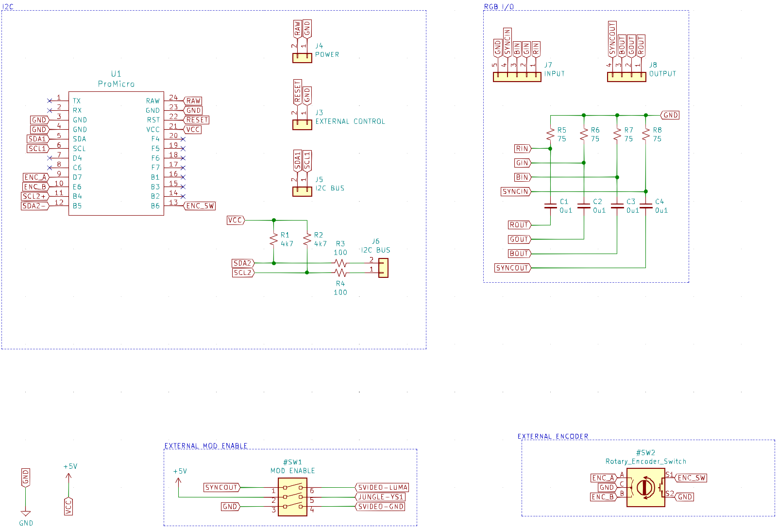
Caution
The RAW pin is getting the 7.5V from the TV, all the rest is using the regulated 5V from the VCC pin from the Pro Micro. The mod Switch can use that same regulated 5V, but we prefer to use some other 5V directly from the TV to avoid mixing up voltages on the wrong place.
The external control header is optional. Having a button for resetting the Pro Micro may or may not be needed at all.
Interrupt the Jungle path with the i2c bus
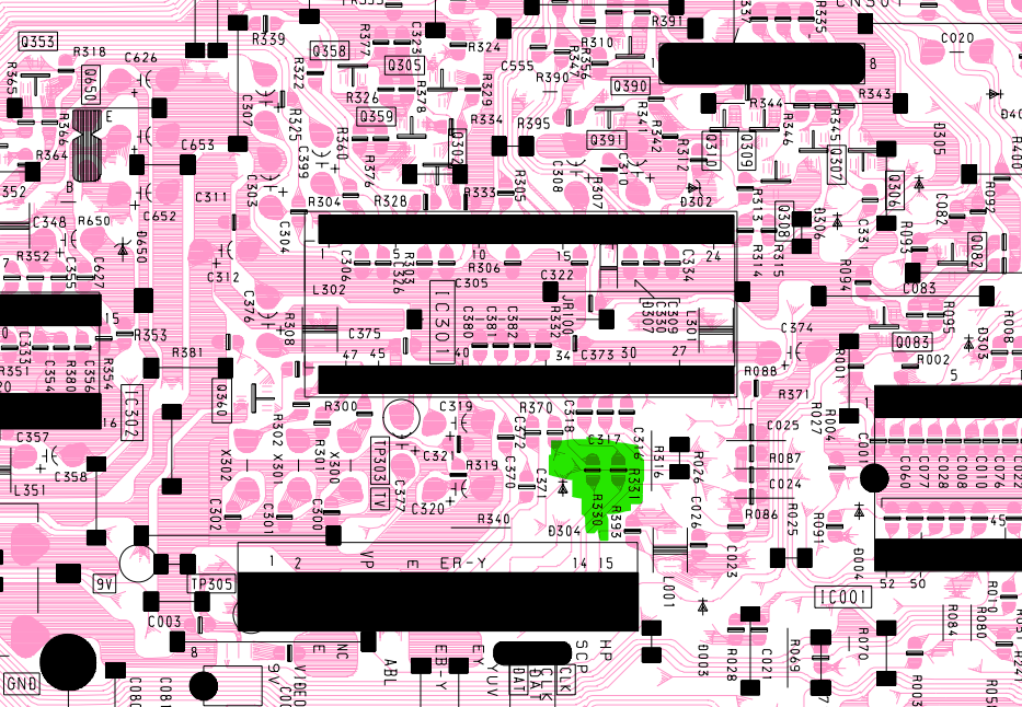
The best way to do that is to remove the two SMD resistors on the bottom side of the main board that are in series with the Jungle’s SDA/SCL lines marked as R330 and R331. They are on the bottom of the board since they are referenced as chip on the schematic and that means SMD.
Unfortunately we were too hasty putting stuff together and ended not snapping photos of the actual PCB but trust me the resistors are there. You will need two wires coming from the Jungle side soldered to those pads and going to the mod.
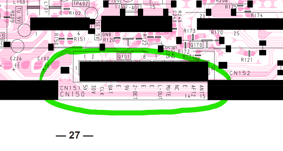
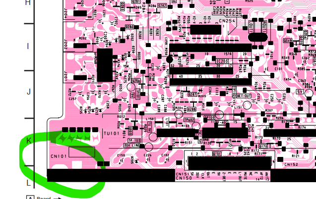
Use the CN150 connector on the left side of the board to also get wires for the SDA and SCL bus connections we will need later.
Find a source for GND, 5V and some standby voltage
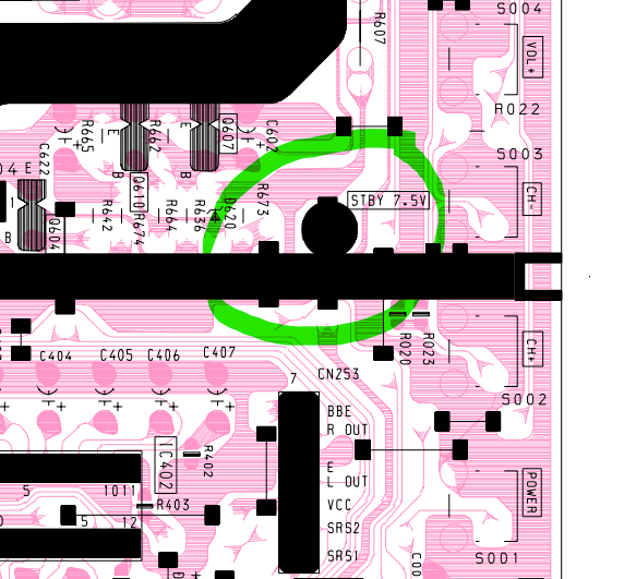
The TV has a 7.5V standby voltage circuit and a 5V one. The 5V one is connected to an IC that has a maximum current that is very low for our plans (100 μA). The 7.5V circuit though, seems to be fine and has an exposed test point that we can solder a wire to.
The GND is easily found using the GIANT CN101 connector on the bottom left of the board, hard to miss a giant blob of solder with a single pin sticking on it.
There are plenty of places with exposed non standby 5V. We will use the left side connector CN150 since there are other stuff that we need there too.
Get the RGB/YS lines
Whatever you prefer, we soldered tiny wires to the underside of the board but it may be easier/more feasible to connect to the pins on the upside of the board. As long as you get the four pins, it doesn’t matter.
SVideo Sync and GND
Using the composite input for sync is feasible, but that makes the image to be really skewed to the right. That was also a problem on the Component video mod, and their solution is still valid here. Refer for the images on the post to see where to solder the sync and GND inputs for that to work (it’s the last image with labels SWITCH and LUMA).
You can also get a S-Video connector and add GND and SYNC to it, making sure the SYNC is going into pin 3 of the connector (Luma).
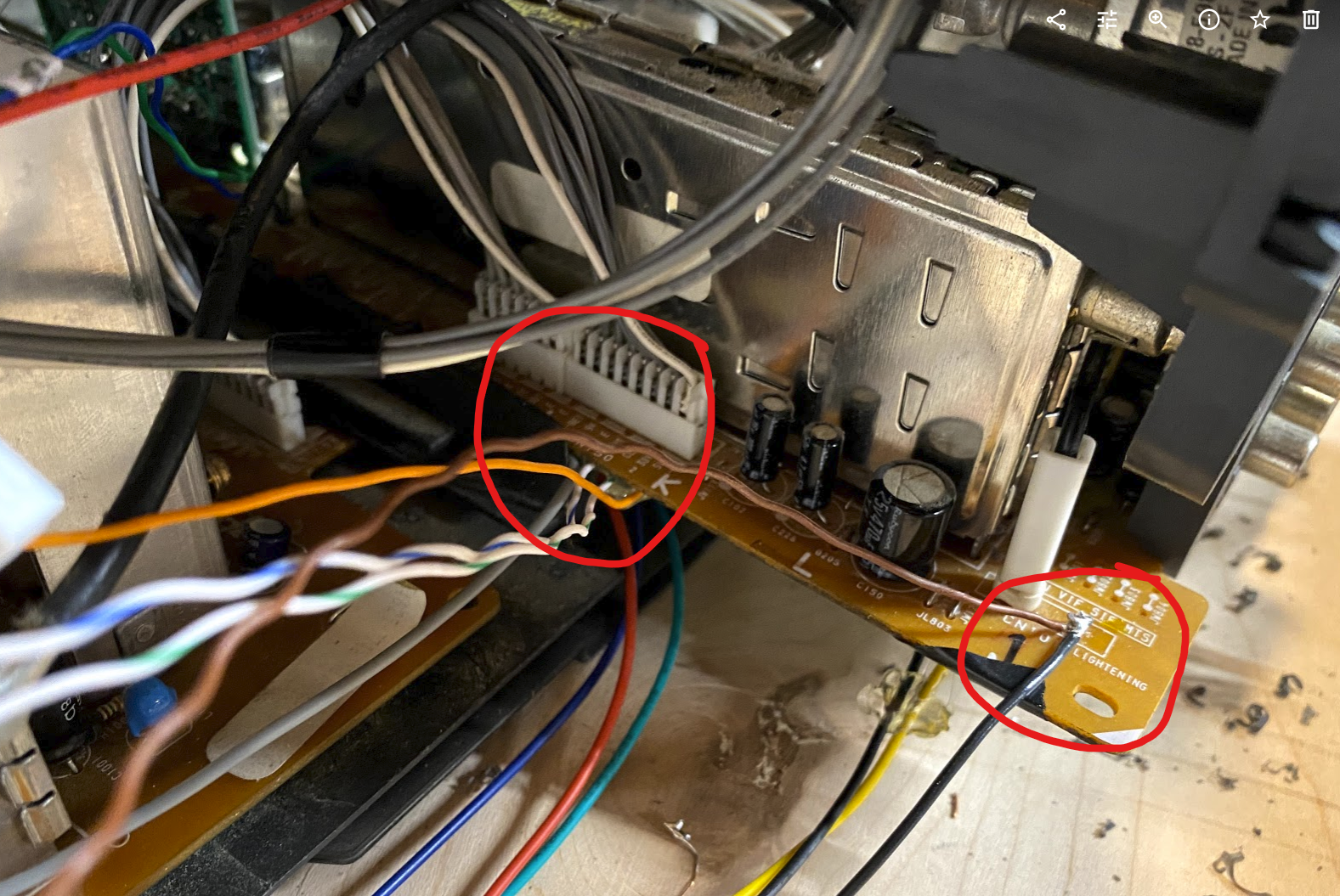
Board image for reference
This is an image of the whole board with the places we mentioned above highlighted. We also circled the Jungle chip position. Remember that this view is from the solder side of the board so it’s upside down.
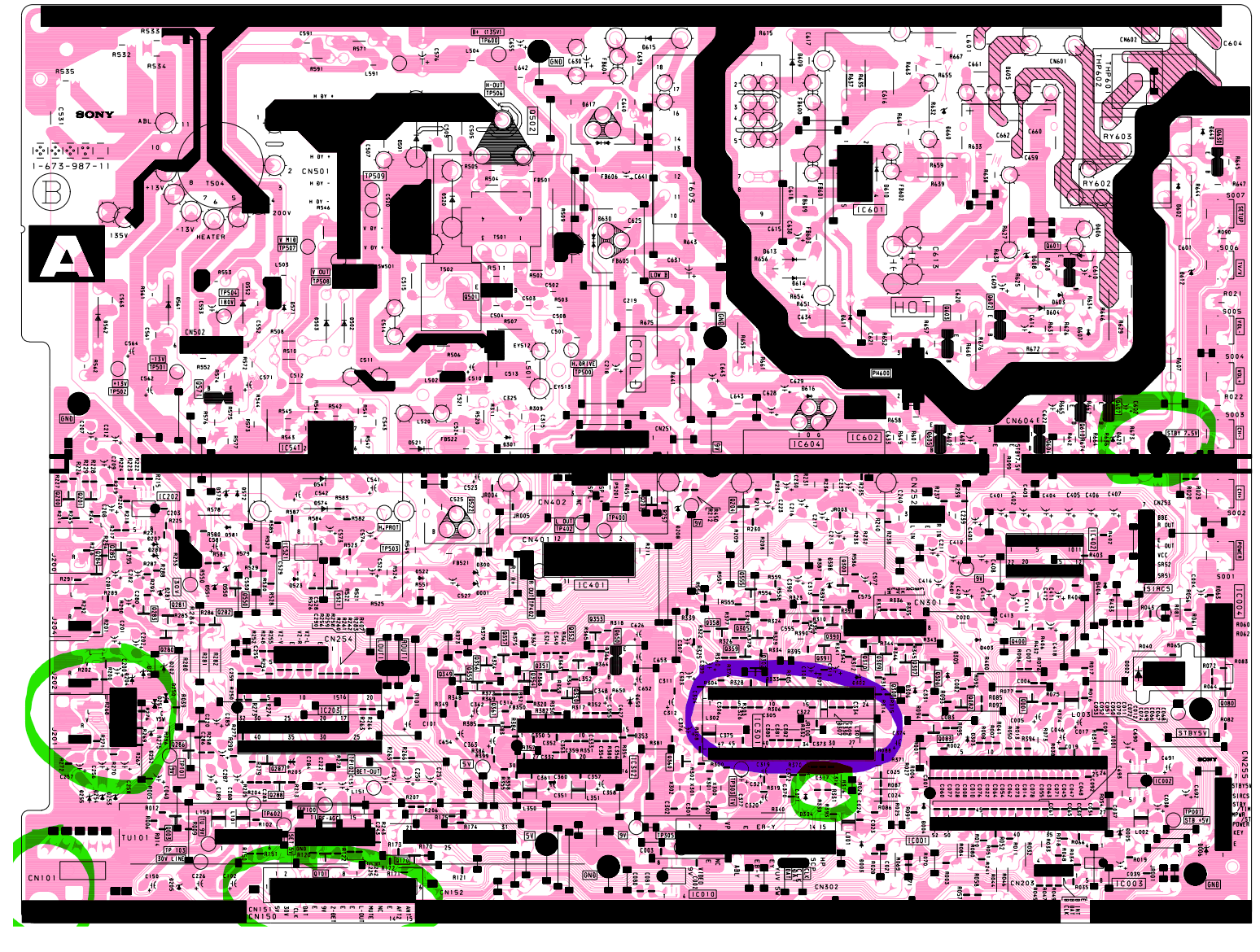
So, for summary:
| What | Why | Where |
|---|---|---|
| 7.5 V Standby | Powering the arduino | 7.5v STANDBY test point (front part of the main board) |
| 5V not Standby | Setting YS1 to HIGH |
Many places, but the CN150 connector is convenient |
| GND | Many things | CN101 is a big GND connector and near CN150 |
| Jungle I²C | Receiver from our arduino I²C | R330 and R331 pads after their removal |
| Main I²C | Receive data from the Micom | CN150 has both |
| LUMA | Input Sync into the S-Video port | S-Video connector pad |
| S-video GND | S-Video input uses GND | S-Video connector pad |
Mod switch
We added a switch as suggested on the Component Video mod to make sure we don’t lose the S-Video input and to be able to disable the RGB input. There will be an schematic with all the connections bellow somewhere.
Encoder support
We added an encoder to the project and the respective code on the arduino side. At the moment all it does is to change the HPOS value so we don’t need to go into the service menu to change that on different MiSTer cores (like the neo geo one). Probably should be easy to add other values and stuff to do that, but then we want to add an LCD and the scope creep is just too much. Feel free to play with it tho.
Final words, thanks and tools
There are probably better ways to make this work, and this may not even be the best image quality for this situation. We have a S-Video connector/adapter and in the end we may use it more than the RGB input, but at a certain point we just wanted to make it work.
None of this would have been able without the help of a lot of people. So thanks Adam/PCBJunkie for responding our numerous emails and providing very good videos, people from the Arduino Discord, CRT Discord that provide a lot of information about how I²C can be worked, and how old TV analog electronics can be flimsy, aside from general encouragement when we were out of our wits with random weird behaviors.
Tools
Things would have been hairy without a logic probe and Pulseview, so yay open source saves the party again. You also should take a look at PlatformIO for embedded/MCU development, it makes it much easier to have a single IDE/environment supporting different boards.
Updates
- 9/1/21 - Added encoder support to change the
HPOSwithout needing to go into the service menu. Should help with pesky out of center MiSTer cores and similar. Updated the schematics PDF and kicad files to reflect that, and also the code on github.