6040 replacement controller
Why and background information
The controller that comes with the usual 6040 CNC (common Chinese model that comes from different brands) is usually a Mach3 based controller with a cracked/pirated software. It also uses some bad dimensioned and straight up dangerous components and electrical choices.
The plan was to make a new controller that I could expand in the future to a different body/frame than the 6040, probably a PrintNC. Ideally, those were the project goals:
- Better grounding on the whole machine
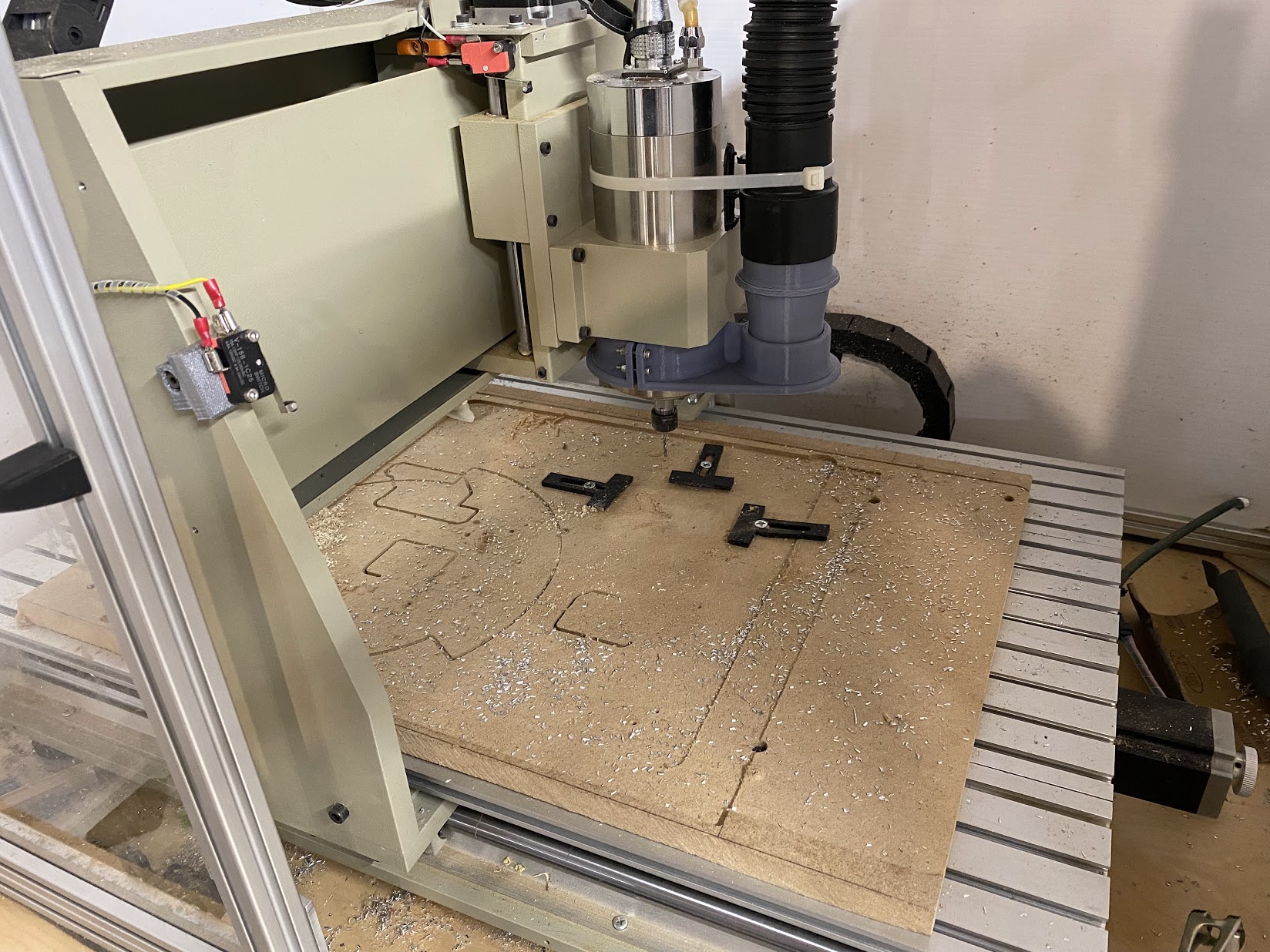
- Adding endstops
- Better resistance to interference from the VFD
- Better power supplies everywhere
- Better stepper drivers
- Automatic controls for water cooling pumps, cooling, and vacuums
- Use LinuxCNC as the controller software
- Add mist cooling
- Provide start/resume buttons for the jobs
I must say that I hit all the objectives of that list, or at least 90% of them  .
.
Software, tools, and and acknowledgements
Of great help on this project were everyone from the PrintNC discord, as well as their wiki. Also, all the electrical plan and schematics were made using QElectroTech.
Hardware
Those are the hardware parts that I used, or changed, during the build:
MeSA 7i96
Since I wanted to use LinuxCNC, using a MeSA card was a given. The 7196 has enough IO ports and stepper controllers to be used on this size, and also uses Ethernet to be controlled, what simplifies a lot the cabling. It also provides a 0-10v interface for spindle control, but I used RS232 for that, so it’s unused atm. It also provides a lot of room to grow, supporting encoders and some more stepper ports.
DM542 stepper drivers
Acquired from Zyltech. Those support much higher voltages than the standard Toshiba that come with the original 6040 controller, and also it’s guaranteed to be using original/checked chips. Those have very good heat dissipation and a good range for current, since I intend to change the stepper motors in the future.
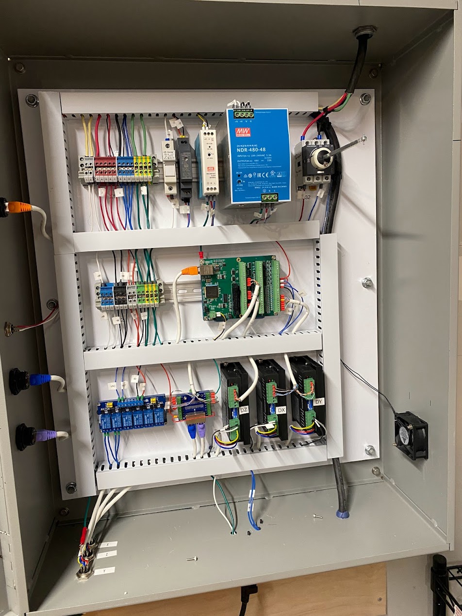
Mean Well power supplies
The way that I organized the power uses three power supplies: 48V for the steppers (and therefore the bigger one), a 12V to be used for the limit switches, and a 5V for the MeSA board and other components that work at this voltage.
All PSUs are connected to the protective ground, and have their GNDs not bonded. Since there’s no signal that crosses the many components, there’s no reason to bind the GNDs and that also provides some more safety and isolation.
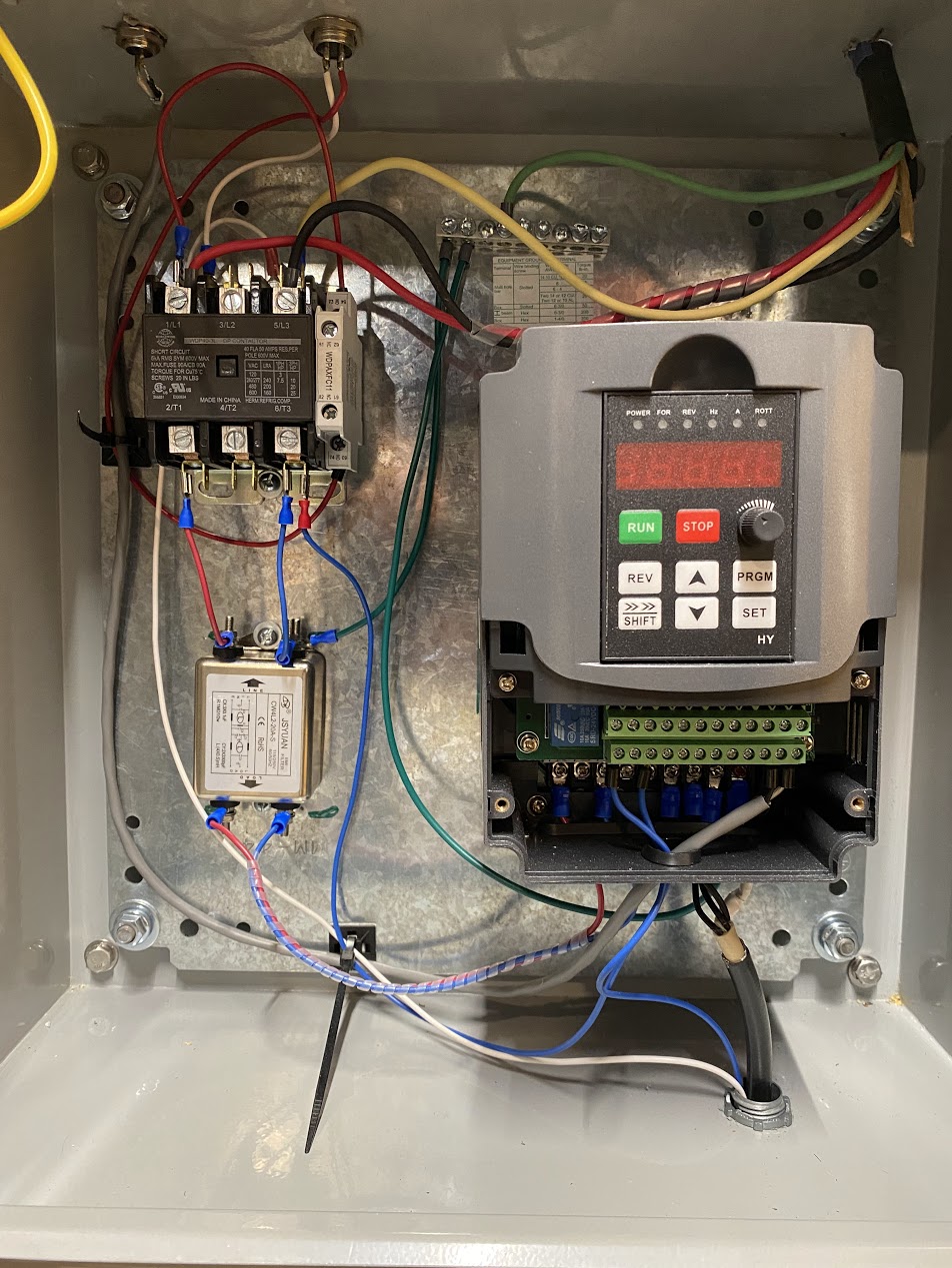
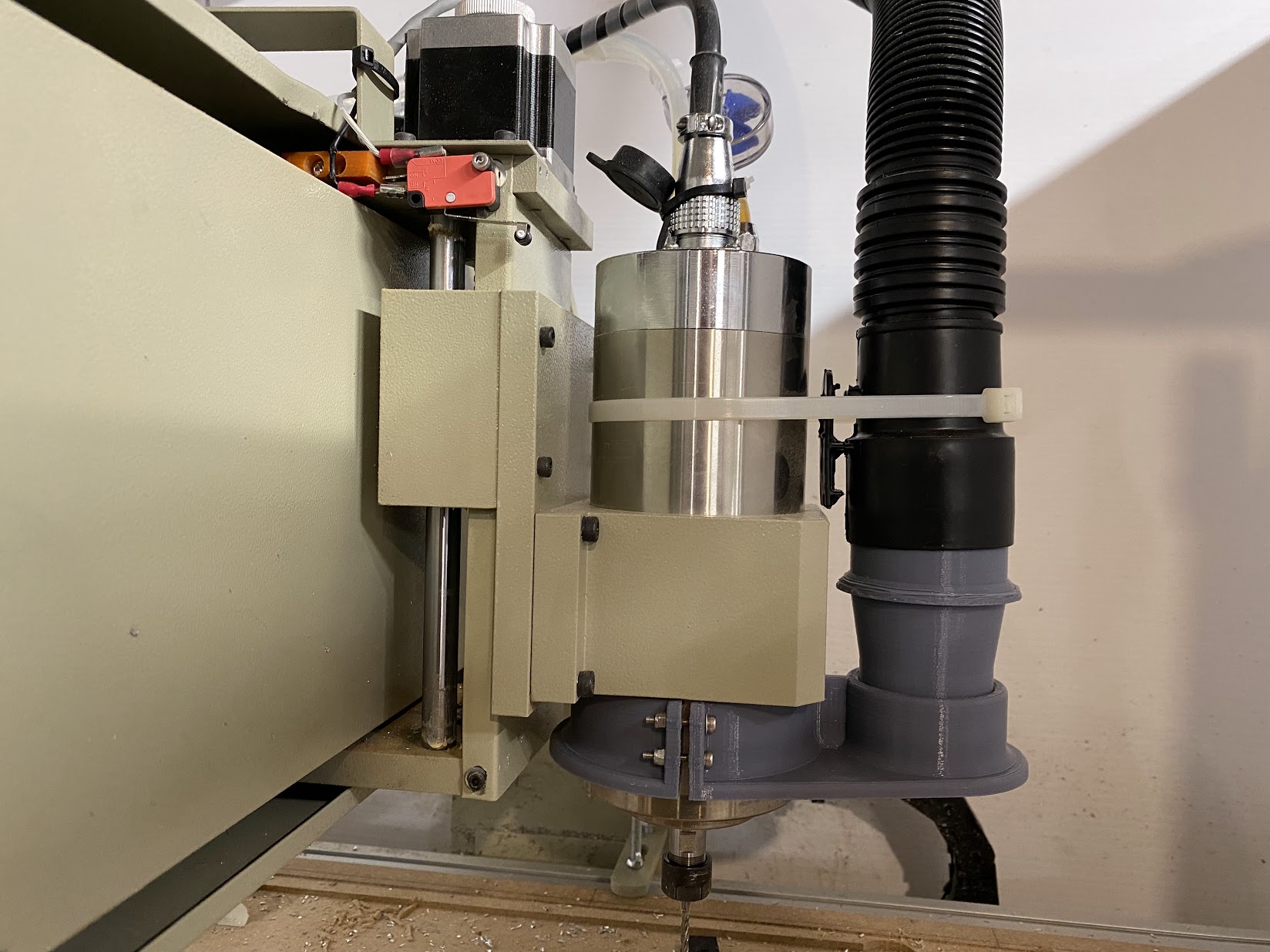
VFD and water cooled spindle
I changed both the VFD and Spindle to 1.5kw (1500W or 2HP). I also made sure to acquire both of those from reputable stores that have a good track record of not selling dubious quality stuff. While the VFD still a Huanyang like many sold around, it is 100% compatible with the LinuxCNC driver hy_vfd what makes configuring it way easier.
The spindle is water cooled, and I made sure that the pump for the coolant (a mix of water and non-glycol anti-freeze) is connected to the VFD so the spindle can’t ever run without the pump being active.
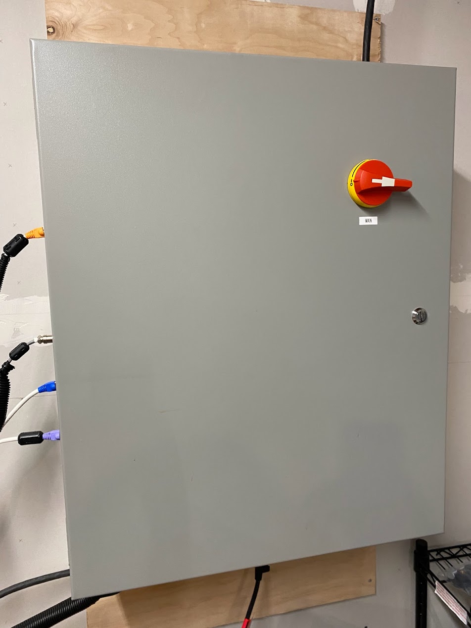
Panel
Since I wanted to separate the VFD from the main control panel, I ended using a smaller panel for the VFD and contactor alone, and a bigger Wiegman’s for the main one.
Cables, buttons, connections, and extras
I replaced all cables goign to the frame for Igus continuous flex. That includes the control cables for the limit switches/probe, the stepper motor cables, and the VFD/Power cables. Also made sure to get all shielded and with an extra earth cable, to make sure I could earth/ground the VFD, frame, and steppers.
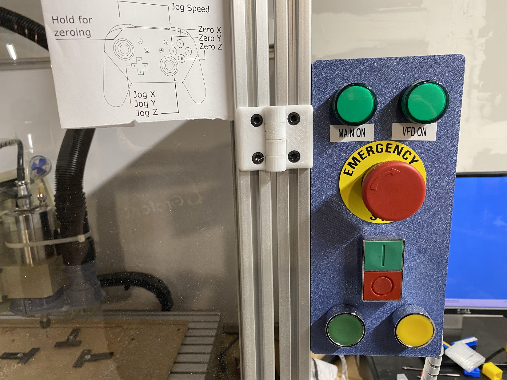
For the safety of all, also included an emergency stop button, mushroom type, as well as fuses for the stepper power, and a safe rotary disconnect switch which allows for the main panel to be closed for the whole operation.
On the VFD panel there’s also an EMI filter, to increase even more the isolation from VFD interference.
Schematics
Luckily, QElectroTech allowed me to make a full schematic for the whole electrical panel and it provided a very good way to verify all the connections and whatnot. Those are the schematics for the whole thing.
They are divided by logical position on the panel, not exactly by how they are organized physically there. The extrusion panel is a reference for the 3D printed panel that I added to the enclosure.
Software
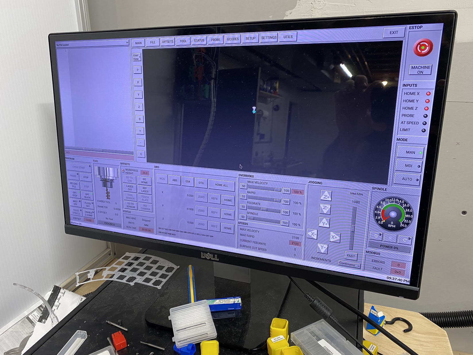
LinuxCNC with qtdragon screen
Using LinuxCNC for the control provides a lot of options and capabilities that are only matched by really expensive professional software. All the config is text based and stored in my github repo. Here are some specific LinuxCNC configs I have added.
Use a joystick to move and jog the toolhead
Link to the specific config file.
This allows me to use an USB joystick to move the toolhead around, fine tune the position for all the axis and also zero the axis on the WCS. To prevent mistakenly pressing a button, those special actions like zeroing and moving will only work when holding one of the shoulder buttons. The back trigger buttons switch the jogging speed so I can move slower to fine tune positions.
I ended adding a cheat sheet near the computer because I keep forgetting what buttons does what.
VFD control via serial port
Link to the specific config file.
This provides better feedback and control for the spindle VFD. It also makes sure the interface is reading the correct values from the VFD since some of those chinese equipments have different measurements out of nowhere. There’s a USB to RS232 adapter on the back of the computer that connects to the VFD’s RS232 port.
Toolchange with automatic tool offset measurement
Link to the specific config file.
Those are actually adapted from the PrintNC Wiki. What it does, after configured on your postprocessor that generates the GCode, is to measure the offset of a tool using a fixed position touch plate at the beginning of a job, and at each manual toolchange repeat those steps:
- Move to a specific position on the bed
- Wait for you to change the tool (with a screen prompt to continue)
- Go back to the touchplate and calculate the new tool lenght/offset
- Return to run the next operation with the tool offset corrected
That makes multi tool jobs way easier on a machine that doesn’t have an auto toolchanger like this one. There’s more information on how to configure it on the printnc wiki page dedicated to this config.
Resume/Start button (doesn’t actually work)
Link to the specific config file.
This was a test to make the Resume/Start button work in a way that’s not complicated, since I have those extra buttons on my enclosure panel. In the end, I saw very little use for it, so it’s now commented out.
Detailed photo gallery
Images are clickable and zoomable.